Electric motor scaling laws and inertia in robot actuators
This is the beginning of a series of posts about robot actuation. The intent here is not to prescribe some specific architecture or solution, but to talk about the fundamentals, with as little bias as I can manage. Hopefully you learn something.
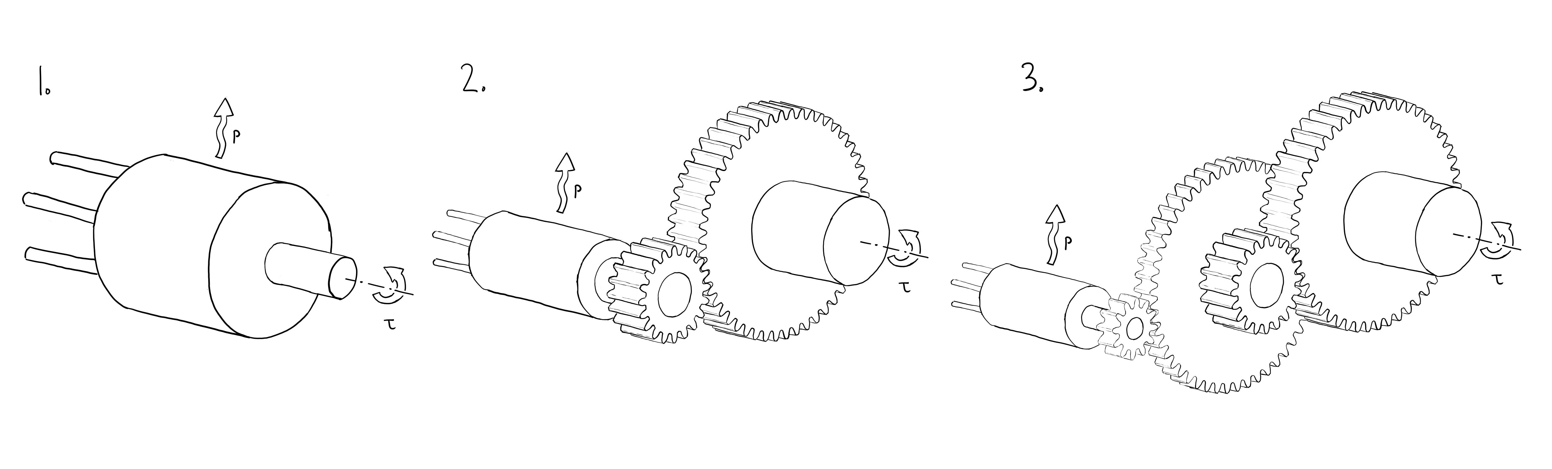
Here’s an ostensibly straightforward question for anyone who’s spent time thinking about robot actuators. Take a look at the three cartoon actuators below. One has a large, direct-drive motor, one has a medium-sized motor with a single-stage gear reduction, and the third has a small motor with a a two-stage reduction. The gear ratios are chosen so that the actuators can all produce the same output torque, and all have the same resistive dissipation in the motor for a given output torque. Assume the gears are massless and 100% efficient.
Which of these actuators has the lowest reflected inertia? Defined as the rotor inertia times gear ratio squared.
We’ll come back to this.
First order motor scaling
How do torque, $\tau$, mass, $m$, power dissipation, $p$, and rotor inertia, $j$, scale with motor size? For this analysis, we’ll assume the radial thickness of the stator & rotor is a constant.
First, what happens if only the length, $l$, changes, keeping the current density in the windings constant (equivalent to keeping the magnetic shear pressure constant)? This is pretty intuitive – double the length of the motor, and torque should double, rotor inertia should double, and power dissipation should double (ignoring end-turns): $$\tau, m, p, j \propto l$$
What if only the radius, $r$, changes, again keeping current density in the windings constant?
$$m, p\propto r$$ $$\tau \propto r^{2}$$ $$j\propto r^{3}$$
A simple figure of merit
“Motor constant”, $K_{m}$, should be a familiar term to anyone who has read a motor datasheet. Motor constant, in units of $\frac{N–m}{\sqrt{watt}}$, describes how much resistive power a motor dissipates for a given torque. This is useful for comparing motors of similar size, but not for comparing motors of very different sizes, since changing the dimensions of a motor directly changes $K_{m}$. It would be useful to have a figure of merit that’s size-invariant.
It turns out it’s straightforward to normalize $K_{m}$ by mass and motor radius. This “normalized $K_{m}$” describes how much force the magnetics can produce for a given power dissipation and mass, and works out to:
$$FoM = \frac{\tau}{r\sqrt{p \cdot m}} = \frac{K_{m}}{r\sqrt{m}}$$
This figure of merit also works for linear motors. Cancel out the meters in Newton-meters with the radius on the denominator, and you get:
$$FoM = \frac{F}{\sqrt{p \cdot m}}$$
It’s also interesting to think about fundamental limits for this FoM. In this classic physics-class Lorentz force example, we have a conductor with conductivity $\sigma$ and density $\rho$ floating in a magnetic field $\vec{B}$.
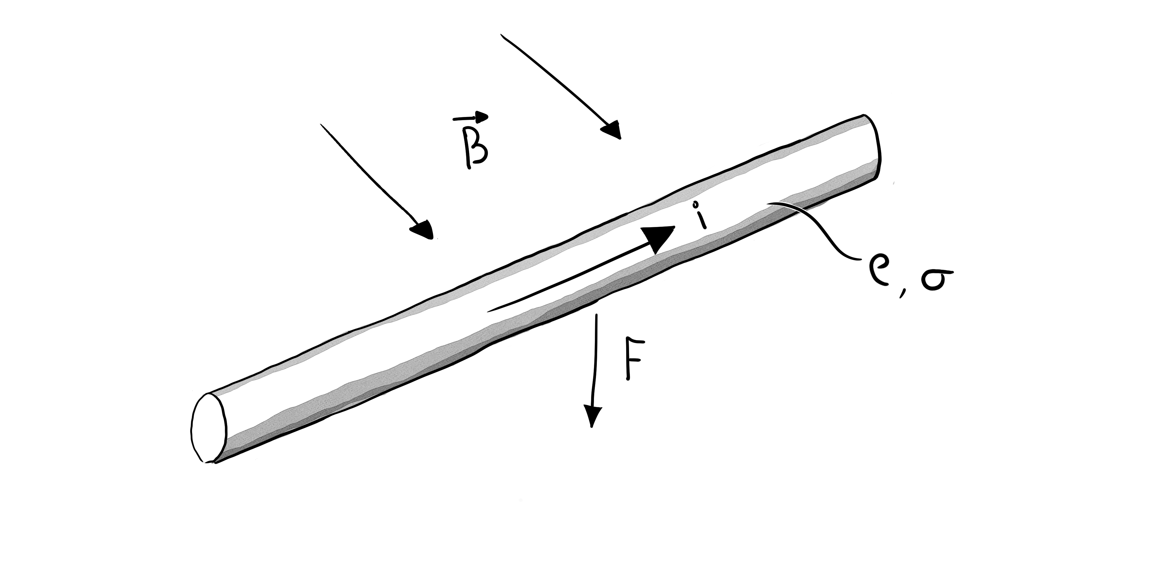
All the lengths cancel out, making the figure of merit just a function of material properties:
$$FoM = |{B}|\sqrt{\frac{\sigma}{\rho}}$$
This sets the upper bound for Lorentz force actuators at around $82 \frac{N}{\sqrt{kg\cdot watt}}$, if the conductor is copper and the magical ambient magnetic field is 1T. There are some clever ways to get around this limit in real motor designs, but that’s a topic for another day.
The linear motor & material-properties versions of these equations can also be found in this paper from Bryan Ruddy and Ian Hunter at MIT.
So, does this FoM work in the real world? Is it actually invariant to motor size and mass? Here’s a plot of normalized $K_{M}$ vs mass for a series of off-the-shelf frameless motors. TQ’s frameless motors make a good case study, since they have a wide size range, similar construction technique across sizes, and accurate datasheets.
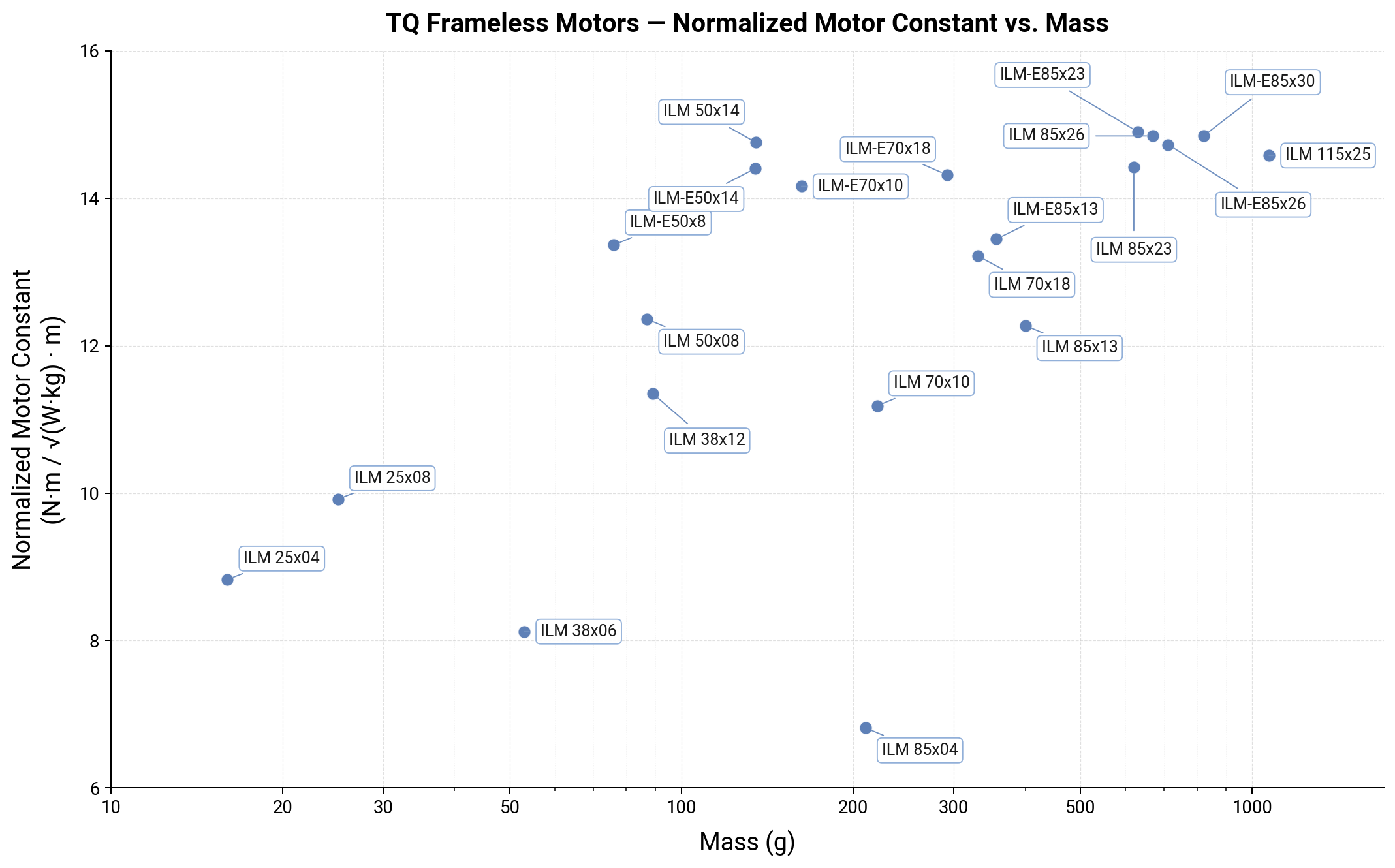
From 16 grams to 1.07 kg, the normalized $K_{m}$ has a range of around 7-15. There are a few outlier low FoM motors, but the bulk of the catalog is between 11 and 15. The low FoM motors are the shortest stack length motors in the catalog. This makes sense: the FoM is only constant assuming first-order scaling, but in reality, shorter stack lengths mean a higher fraction of the motors’ winding resistance and mass is in the end turns, and other end-effects like rotor & stator flux leaking out of the axial faces of the motor become more significant.
Combining scaling, FoM, and gear ratio
How does this figure of merit relate to reflected inertia, $j_{ref}$, and gear ratio?
From the geometric scaling laws above $j \propto mr^{2}$. Re-arranging the FoM, $\tau \propto r \sqrt{mp}$. Combining these, $\tau \propto \sqrt{jp}$
In an actuator with a gear ratio $G$, $\tau_{out} = G\cdot \tau$, and $j_{ref} = G^{2}j$
So:
$$j \propto \frac{\tau^{2}}{p},\quad \frac{j_{ref}}{G^{2}} \propto \frac{\tau_{out}^{2}}{G^{2}p}, \quad j_{ref} \propto \frac{\tau_{out}^{2}}{p}$$
And would you look at that, the gear ratio dropped out! With this simplified scaling, for a fixed torque reflected inertia is only a function of power dissipation!
This is not intuitive. Here’s a concrete example.
Actuator 1 is direct-drive, has an output torque of 1 N-m, a mass of 1 Kg, a power dissipation of 1 Watt at 1 N-m, and a rotor inertia of 1 $kgm^{2}$.
Actuator 2 has a motor 1/2 the diameter and the same length as the motor in actuator 1. At the same power dissipation, the motor produces $\frac{1}{2\sqrt{2}}$ times the torque, so it needs a gear ratio of $2\sqrt{2}$ to produce the same torque at the output of the actuator. The rotor inertia is 1/8th that of the motor in actuator 1, since $j\propto r^{3}$. The reflected inertia after the gearing is $g^{2}j = \frac{(2\sqrt{2})^{2}}{8}= 1$.
One of the original Cheetah actuation papers says essentially the same thing:
in a design space where the motor mass and the continuous torque requirement are held constant while the gap radius is free to vary and the massless and frictionless gear train are added to meet the torque requirement, the output torque and total reflected inertia are independent of the gap radius and corresponding gear ratio
This is actually true even when mass is not held constant – the assumption in this paper though is that the ability to dissipate heat is $\propto$ mass, which is why they held mass constant.
Using the TQ motor data again, we can see how things look back in reality. The plot below shows a suite of actuator designs with the same output torque, different motors, and a swept range of gear ratios. For each motor and range of gear ratios, the power dissipation required to hit the output torque and resulting reflected inertia are plotted. Individual motors are only plotted up to their peak torque rating, so that all the points in the plot are feasible.
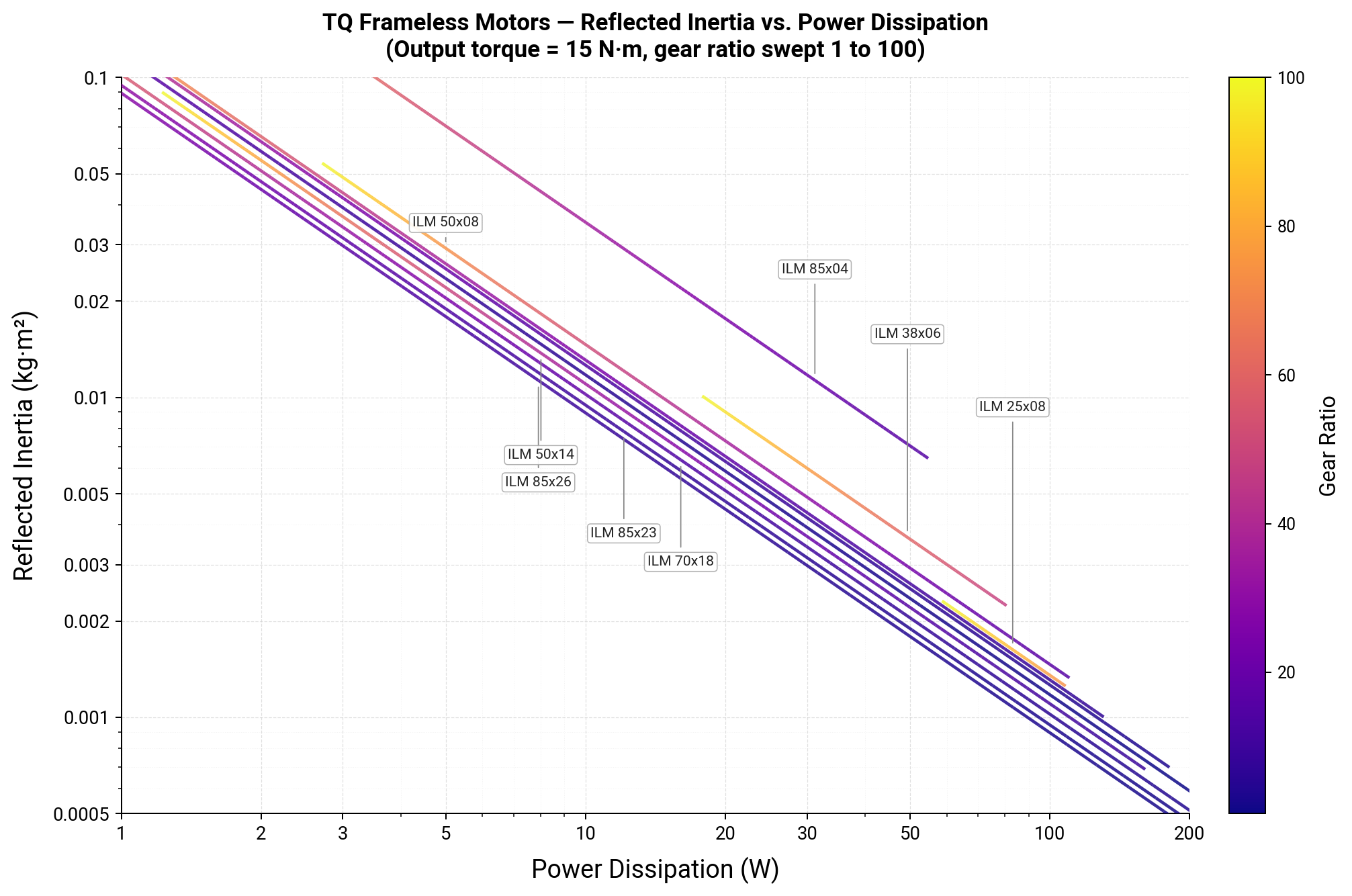
Excluding than the short stack length motors (again), there’s not a huge spread between the whole catalog of motors. For the same torque and a given power dissipation, the reflected inertia after gearing is the same to within a factor of about 1.5. Even though the gear ratios and motor masses vary by ~2 orders of magnitude!
This plot could be almost entirely condensed into a single number per motor, by using the rotor mass as the mass in the FoM, rather than the mass of the entire motor, and the rotor radius as the radius in the FoM.
But what about [outrunners/axial flux/double-sided stators/transverse flux]?
In general, motor topology does not significantly affect FoM.
There are exceptions to this – transverse flux motors in particular are interesting because they aren’t bound by the Lorentz-force limit shown above (though they have their own challenges). Motor topologies are probably worth a post of their own in this series.
Why is an axial flux motor essentially the same as a radial flux motor? They are both just linear motors wrapped around different axes.
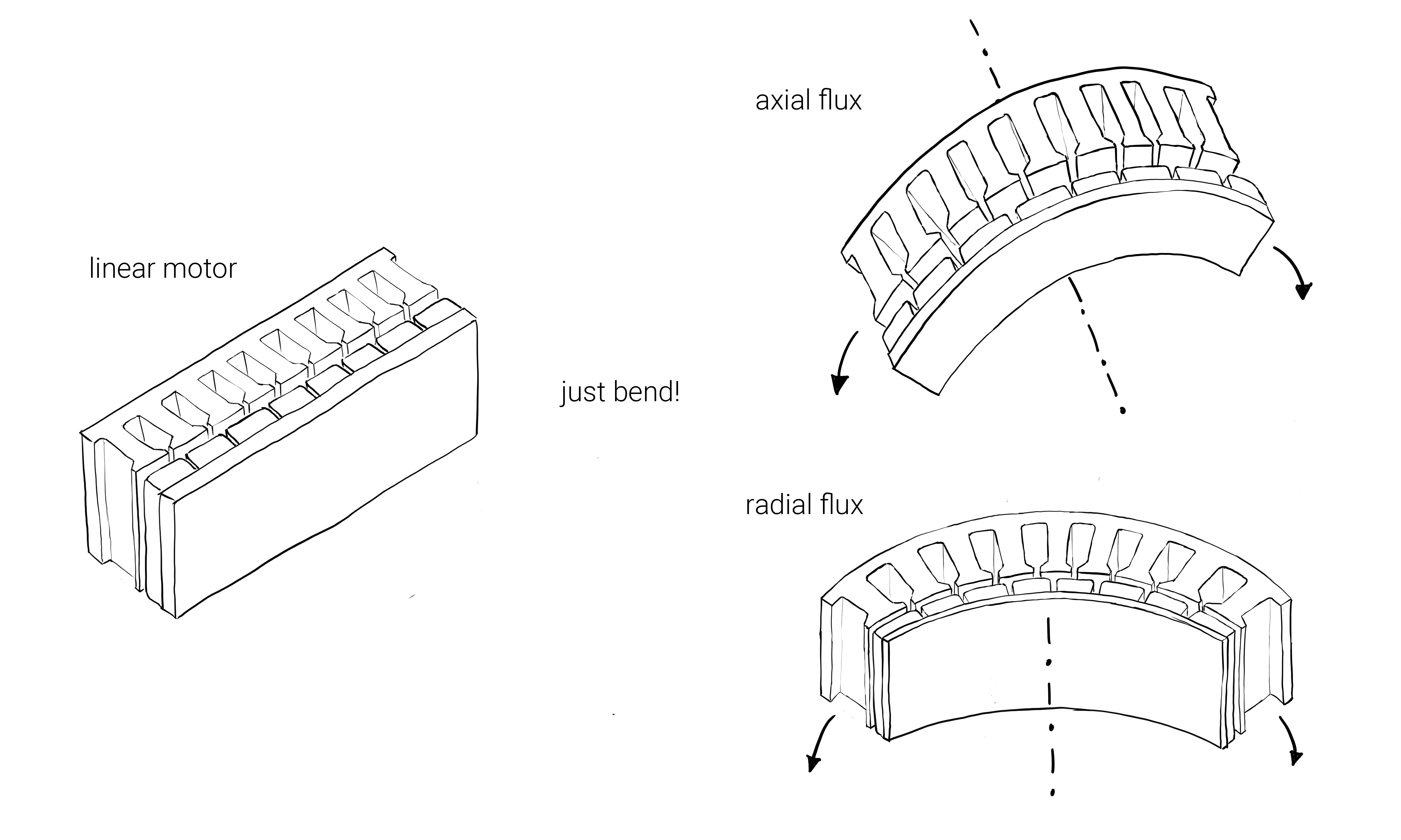
(if you wrap the linear motor about the final axis, parallel to the linear motion, you get a tube motor)
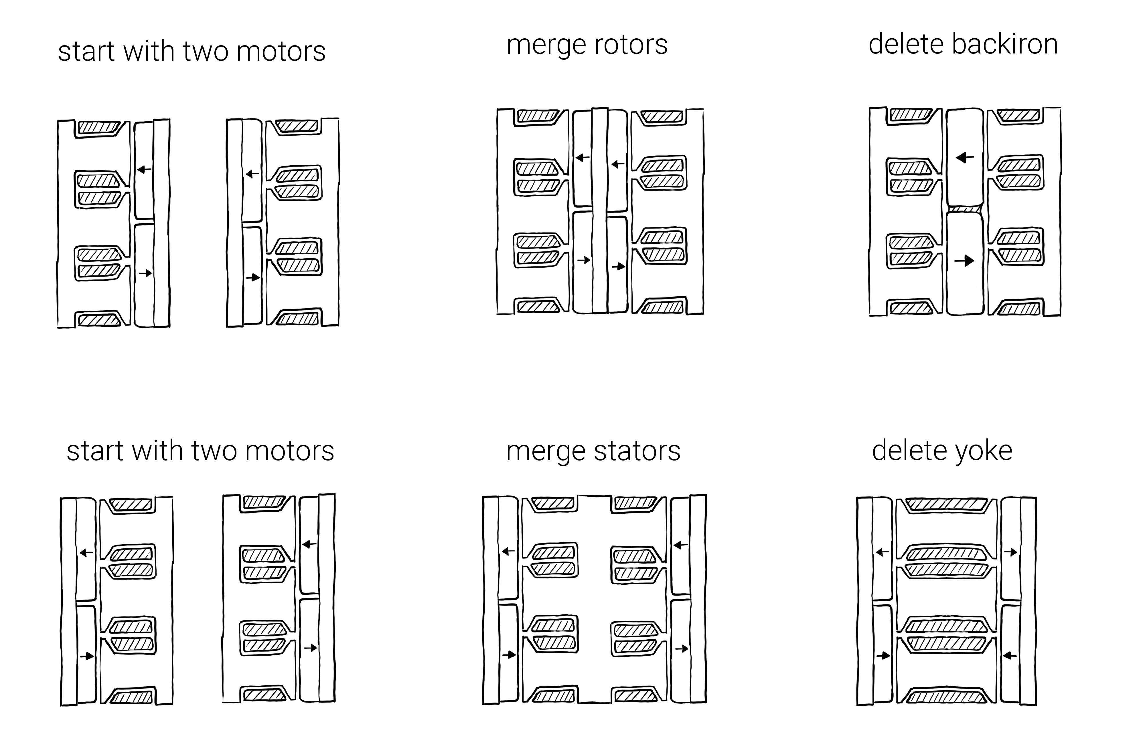
What about double-sided rotors? Do double-sided rotors give you twice the torque and twice the FoM? Congratulations, you’ve made two motors and stuck them together! In certain arrangements (e.g. YASA), there is an advantage (and structural challenges added) vs literally slapping two motors together, from removing the “yoke” of the stator (or rotor backiron, in a double-stator motor), hence the “Yokeless” in Yokeless And Segmented Armature. This can be significant in terms of mass & volume, especially in low pole-count motors where the yoke & backiron have to be thick.
Take the EMRAX 208 as a double-rotor, YASA-style example. It’s about 10X the mass and 2X the diameter of the largest TQ motor in the plots above. I took a similar motor apart a while back. Conservatively assuming that the packaging (housing, bearings shaft, etc) is 50% of the total motor mass (it’s likely much less), the normalized $K_{m}$ would be 13.9. Right in the ballpark of all the TQ motors.
What’s missing?
This is not an end-all be-all metric. It says nothing about peak torque and saturation, and it says nothing about rotor inertia, and it says nothing about heat transfer.
The astute reader may have noticed that in the example above, the 1/2 radius motor has to dissipate the same amount of power, with only 1/2 the surface area available! The 1/2 diameter motor example above is also driven harder in terms of current density and flux density than the direct drive example – the shear pressure it needs to produce is $\sqrt{2}$ times higher.
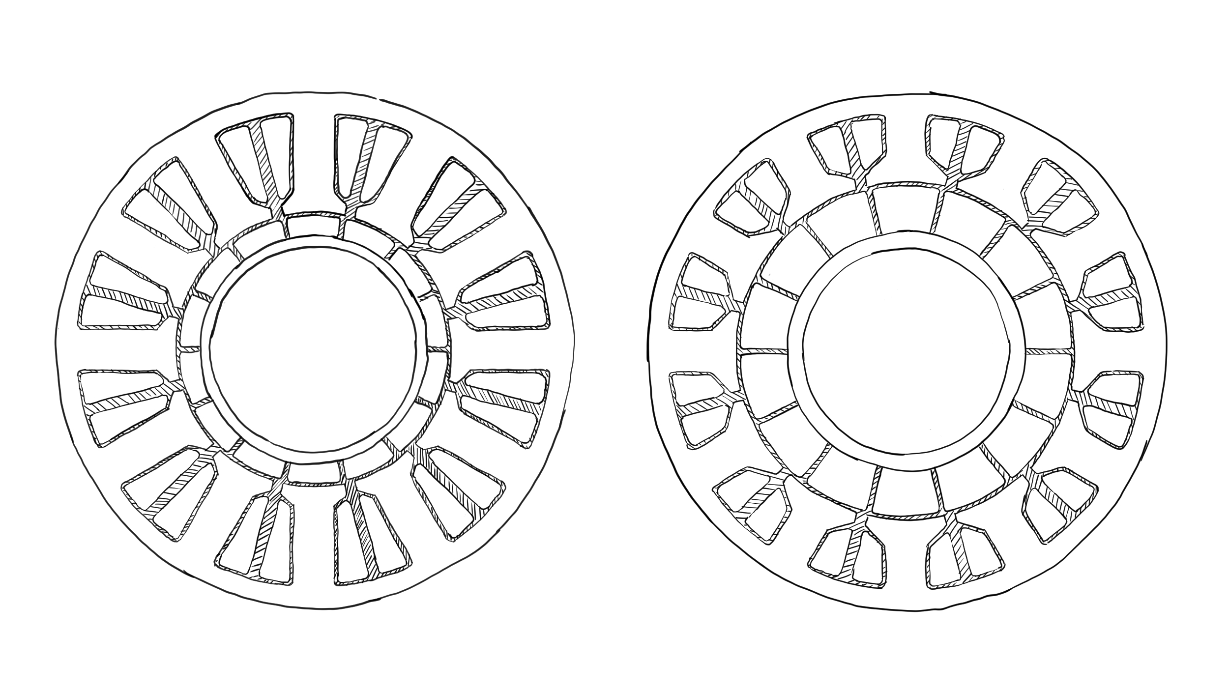
The FoM as-written doesn’t say anything about inertia – within a given family of motors, the FoM will be approximately the same, and the resulting actuator inertia for a given torque & power will be approximately the same, but that doesn’t mean that every motor with that FoM has the same inertia. For example, the two motors illustrated below could have the same bounding dimensions and normalized $K _{m}$, but have very different rotor inertias.
The gear-ratio and inertia analysis here assumes gears are zero mass, zero inertia, and perfectly efficient. This is obviously not how real reductions work, though some types of reductions can achieve high gear ratios with relatively high efficiency and minimal added inertia.
Wrapping things up
- Motor constant can be normalized by mass and radius to get a metric of how efficiently a motor produces force for a given amount of magnetic material. This is useful for comparing motors of very different sizes.
- Reflected inertia is primarily determined by power dissipation at a given torque, not gear ratio or motor size.