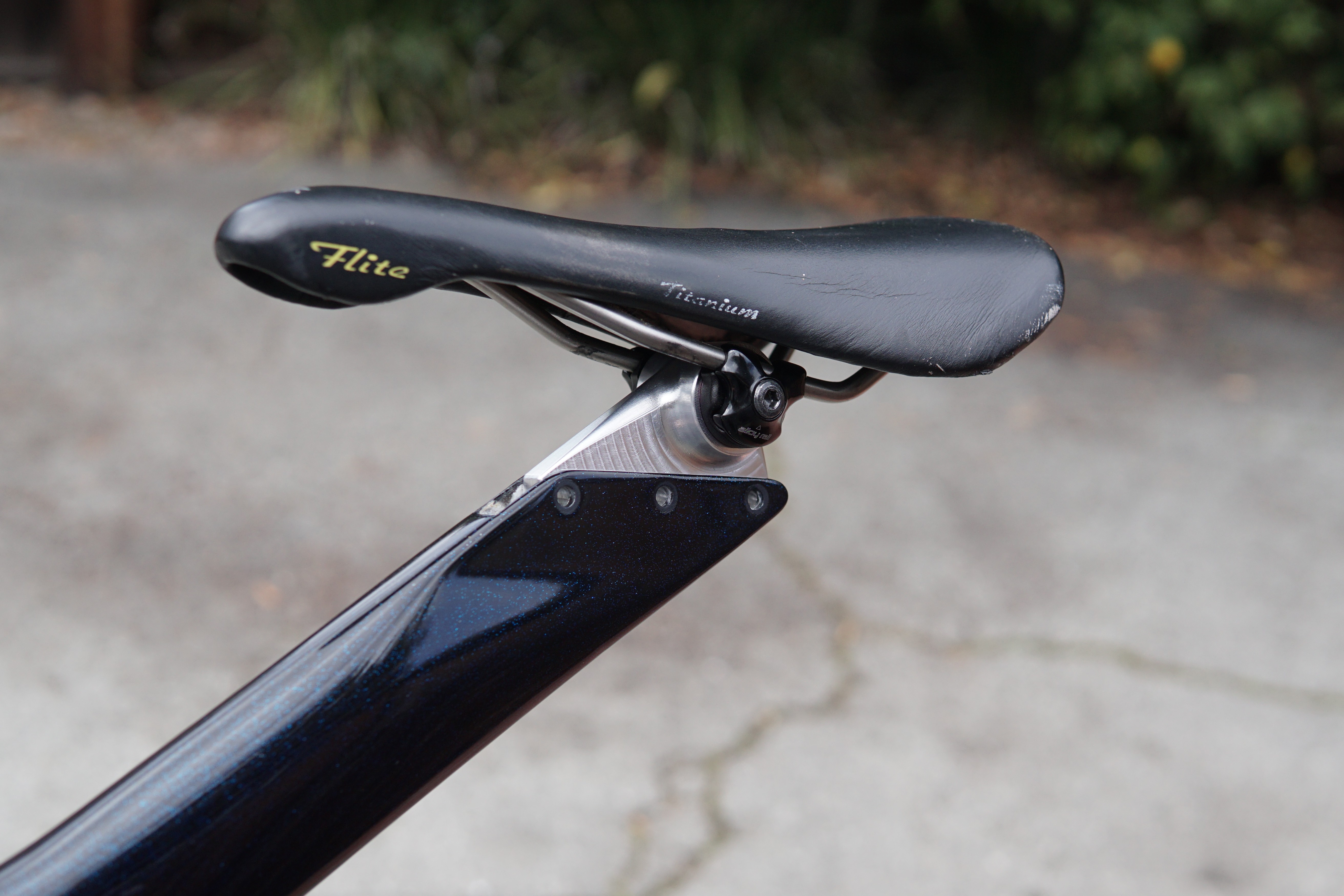
Machining a saddle clamp for the Zipp
The original saddle clamps on the Zipp 2001’s were not very well designed, and the clamp that came with my frame (like many) was broken. The originals have 2 major problems: 1) The screws that clamp the rails on the saddle are tightened counterclockwise, not clockwise - I’ve seen stripped out screws because of this on a couple clamps. You think you’re loosening the saddle clamps, but you’re actually tightening them. 2) The saddle pitch adjustment relies on a pinch bolt clamping a cylinder. These would slip, so people would over-tighten the pinch bolt and crack the clamp.
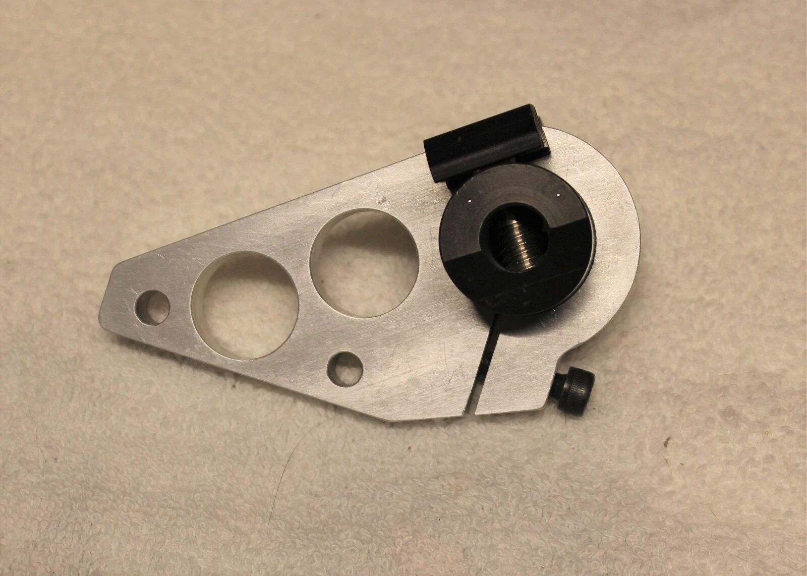
Here’s what one of the original clamps looks like. Some (like the one I have) have a counterbore for the pinch bolt, which leads to a locally very thin wall, where a crack starts. The example below may be a later version as it doesn’t have the counterbore.
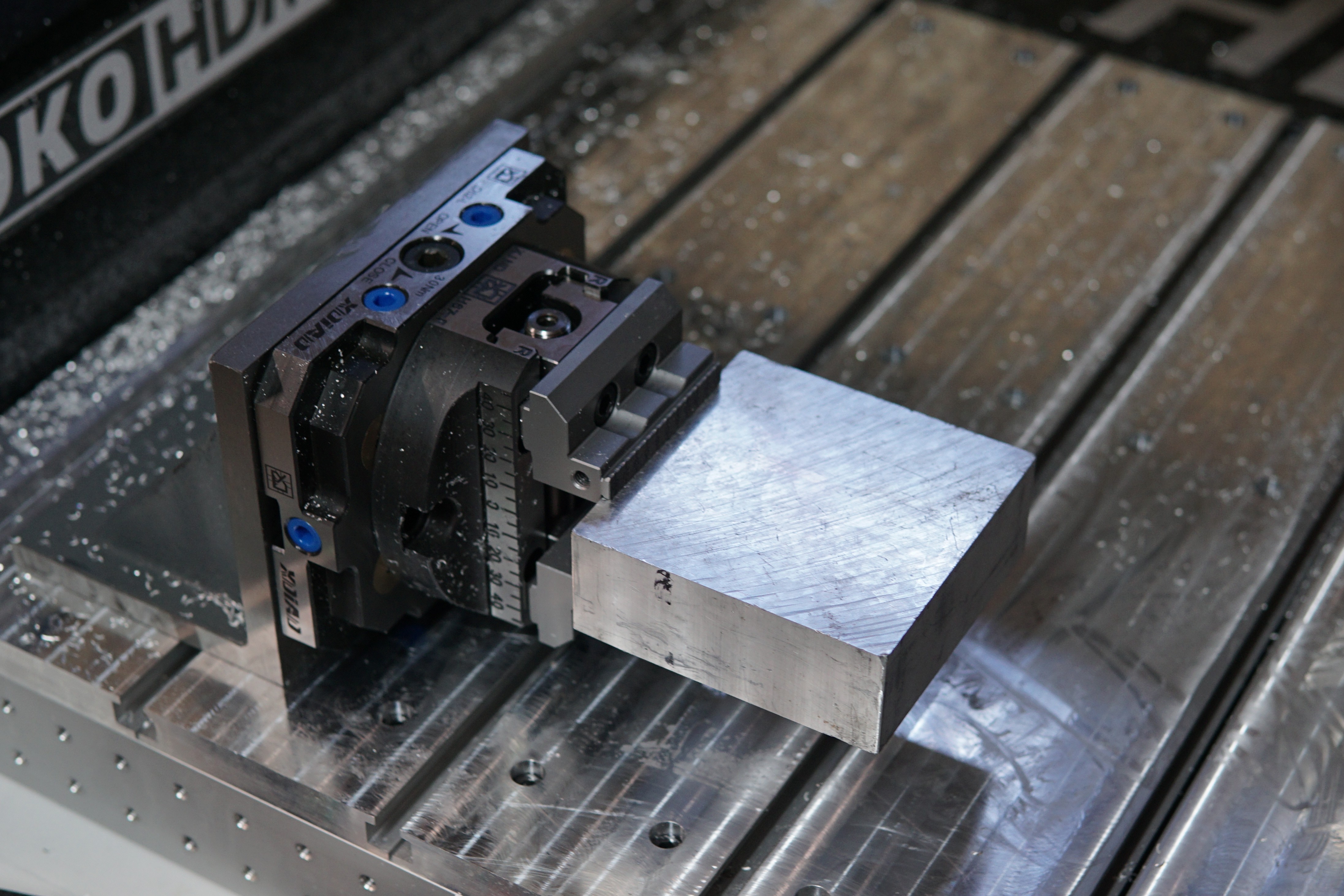
This is an awkward part to hold for a second operation, and I recently replaced my little 5-axis mill with a beefier benchtop router. To mimic the 5-axis workflow, I got some Lang-style zero point fixtures from Xindian. I have one fixture mounted at a right angle on the router table, so I can index parts around every 90 degrees and access 4 sides, and another one bolted to the table so I can access the 5th side of parts. I also got a third round one to put on the lathe, so I can make mill-turn style parts, but I haven’t used that one yet.
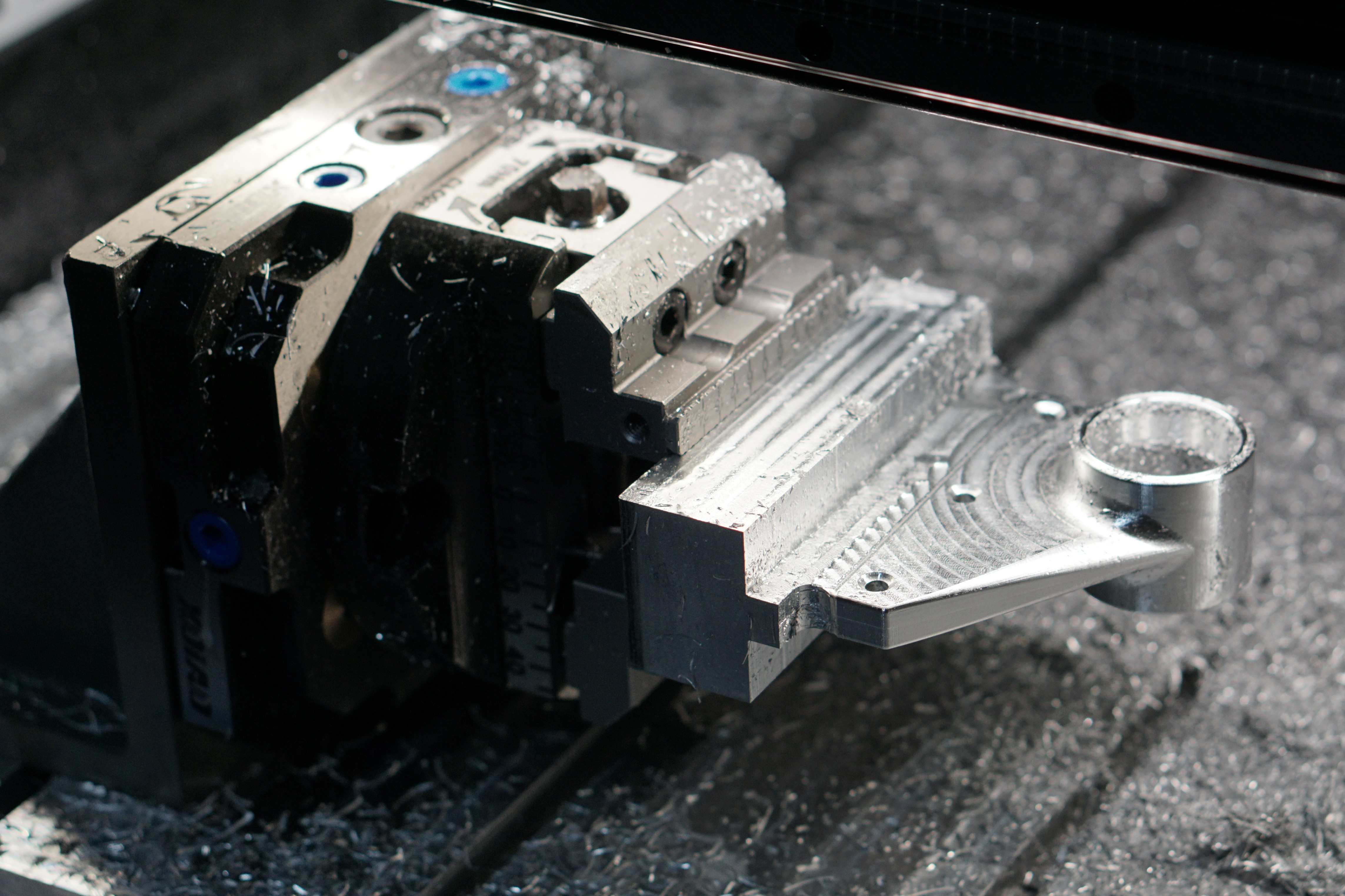
Here’s the brick of aluminum set up for machining. The self-centering is also a Lang knock-off from Xindian.
After finishing the first operation:
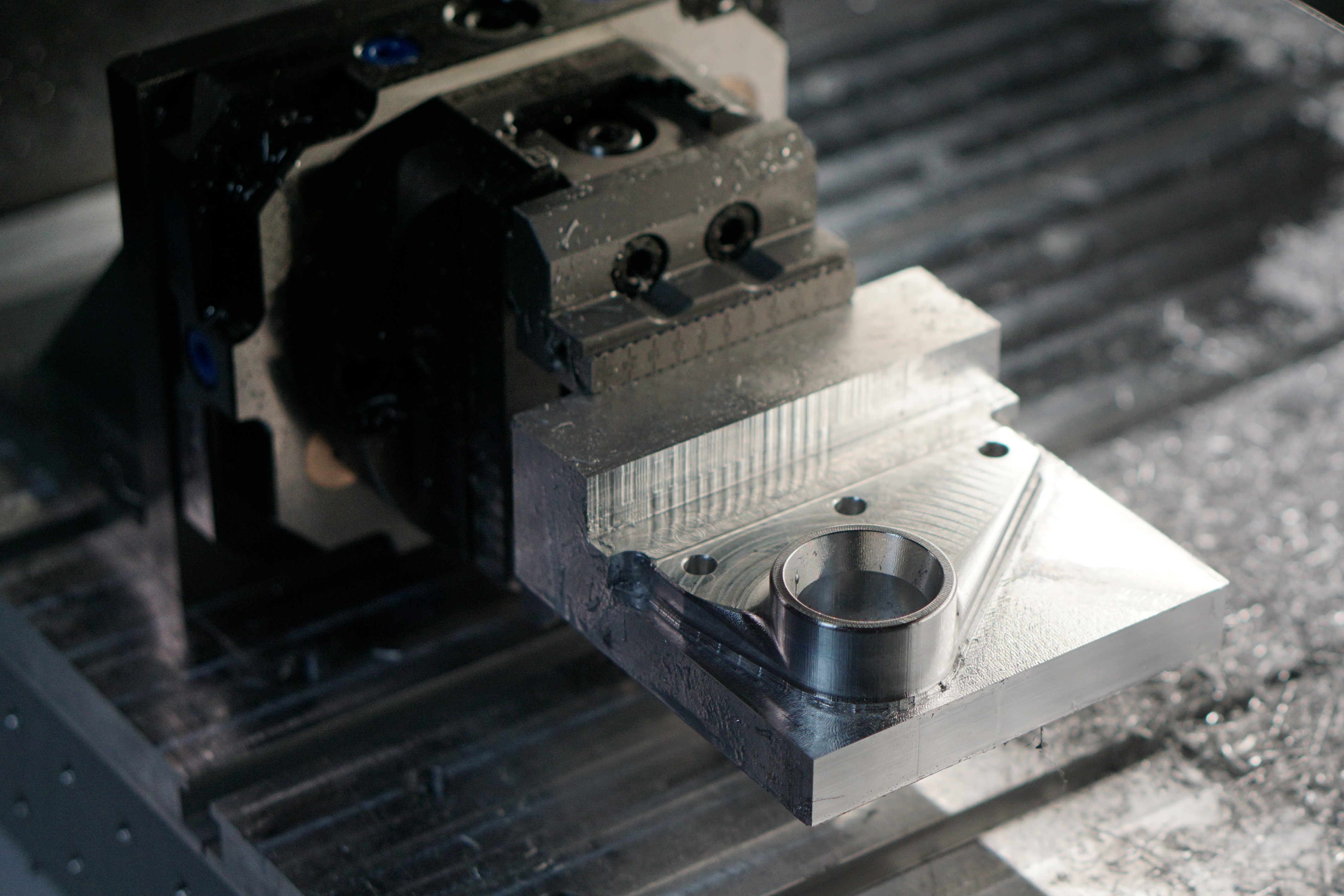
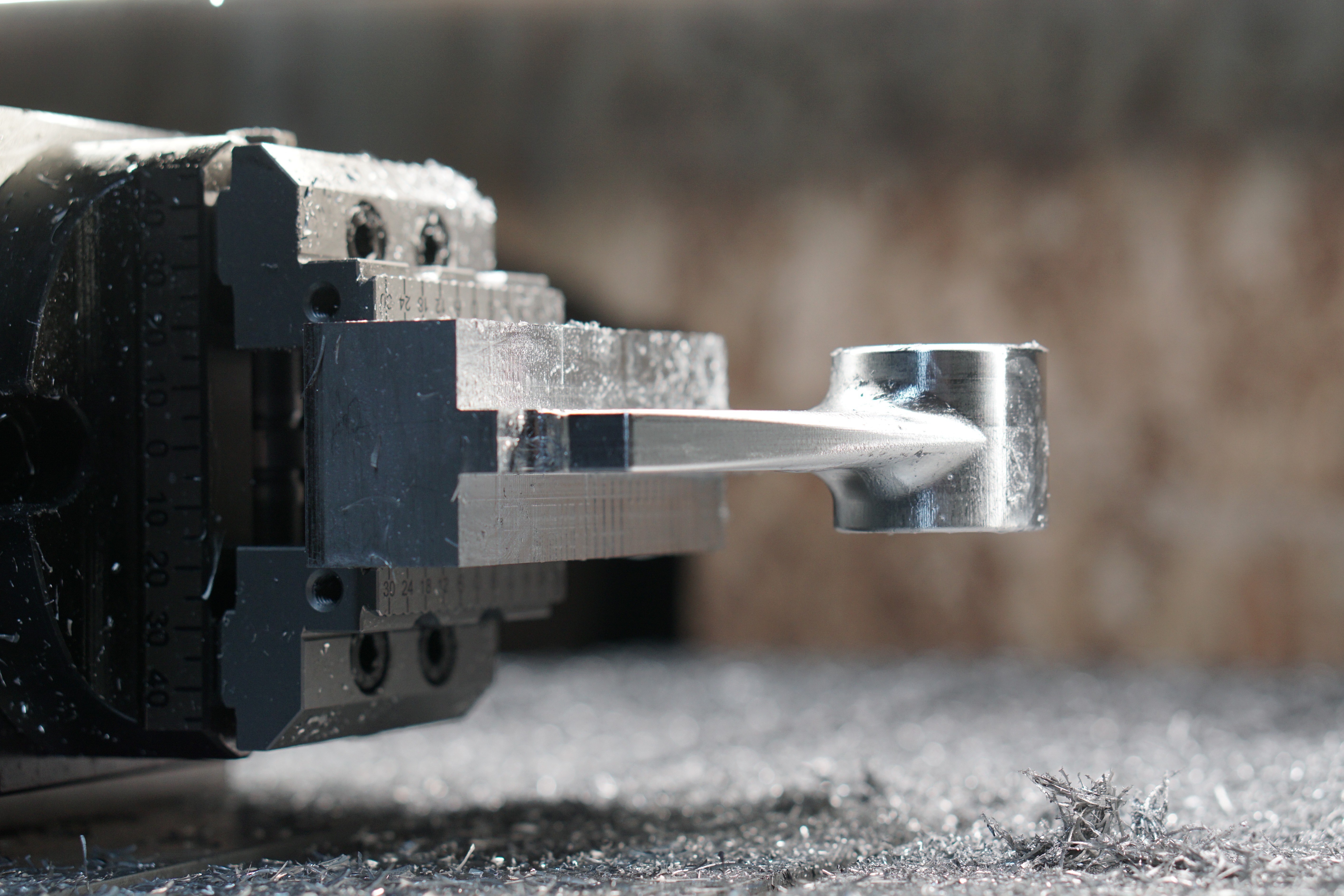
After the second op, before parting it off:
And here’s a little video of the machining process:
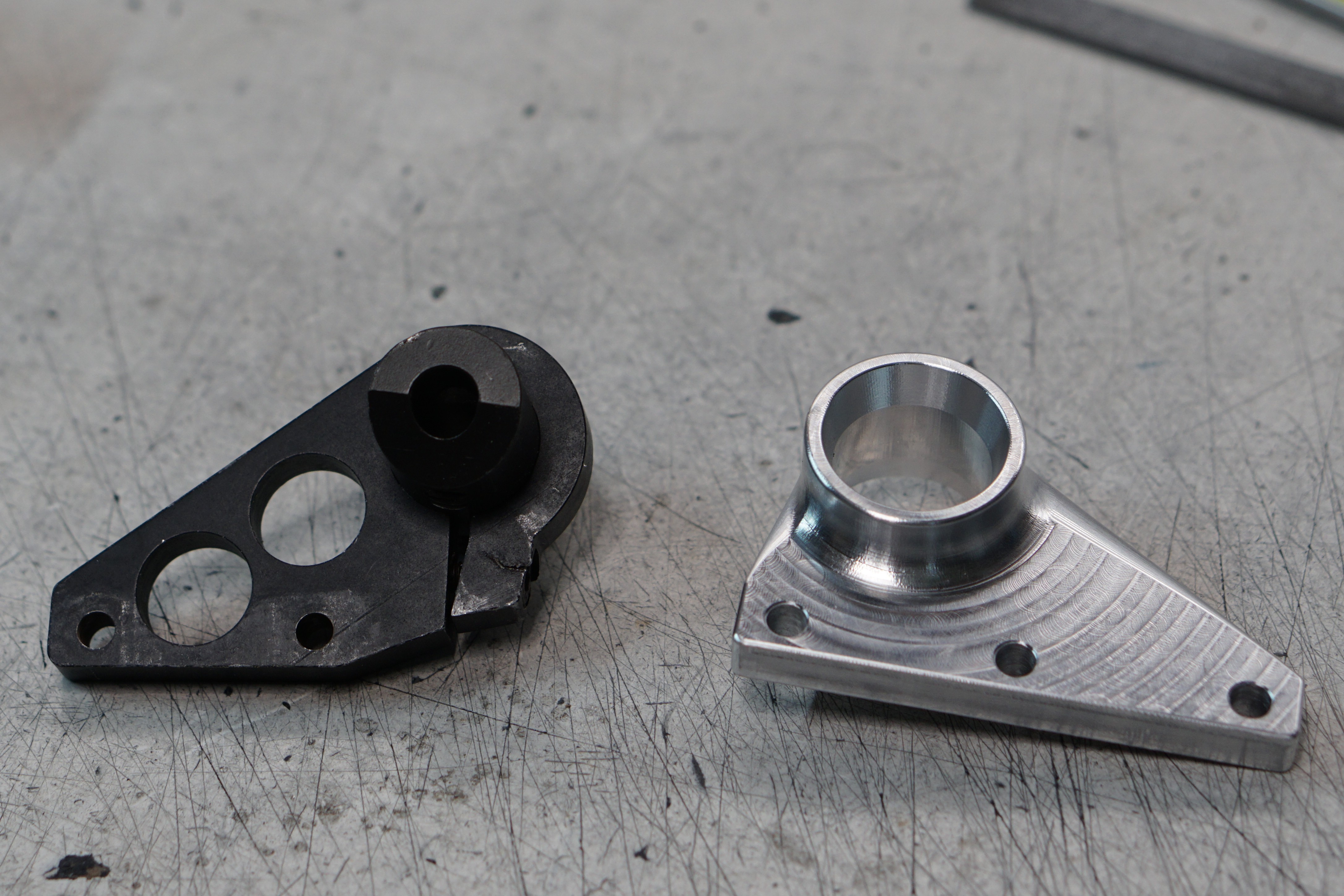
This is what the finish part looks like, next to the original clamp. Notice the crack through the pinch bolt counterbore in my original clamp:
For hardware, I’m using replacement clamping hardware from Specialized
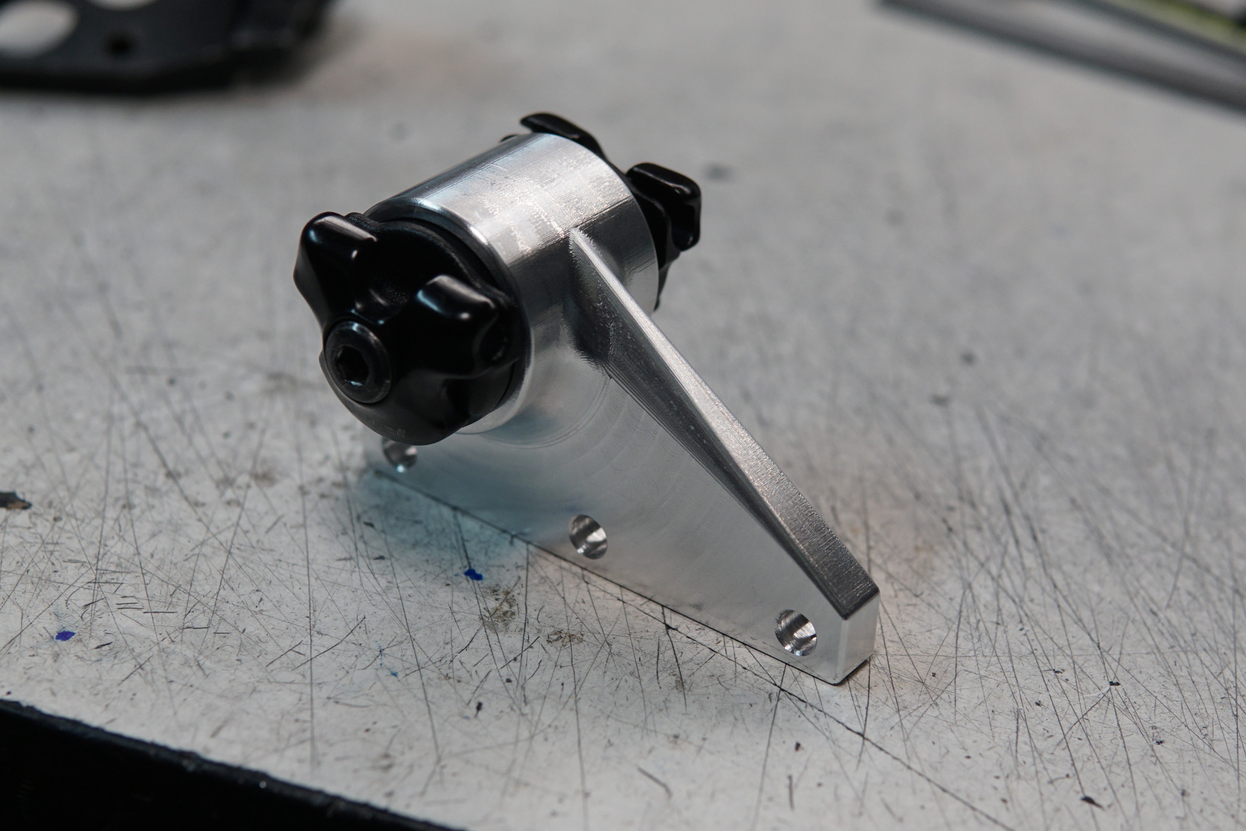
Installed on the seat beam: